Skip to content

Lighting

Gloam

Small oval fixtures lined up along a ceiling beam. Each holds an amber and a warm white LED; dim them separately or run them together. One ESP8266 board drives the whole line; run it from its own page, a wall switch or Home Assistant. No cloud, no account.

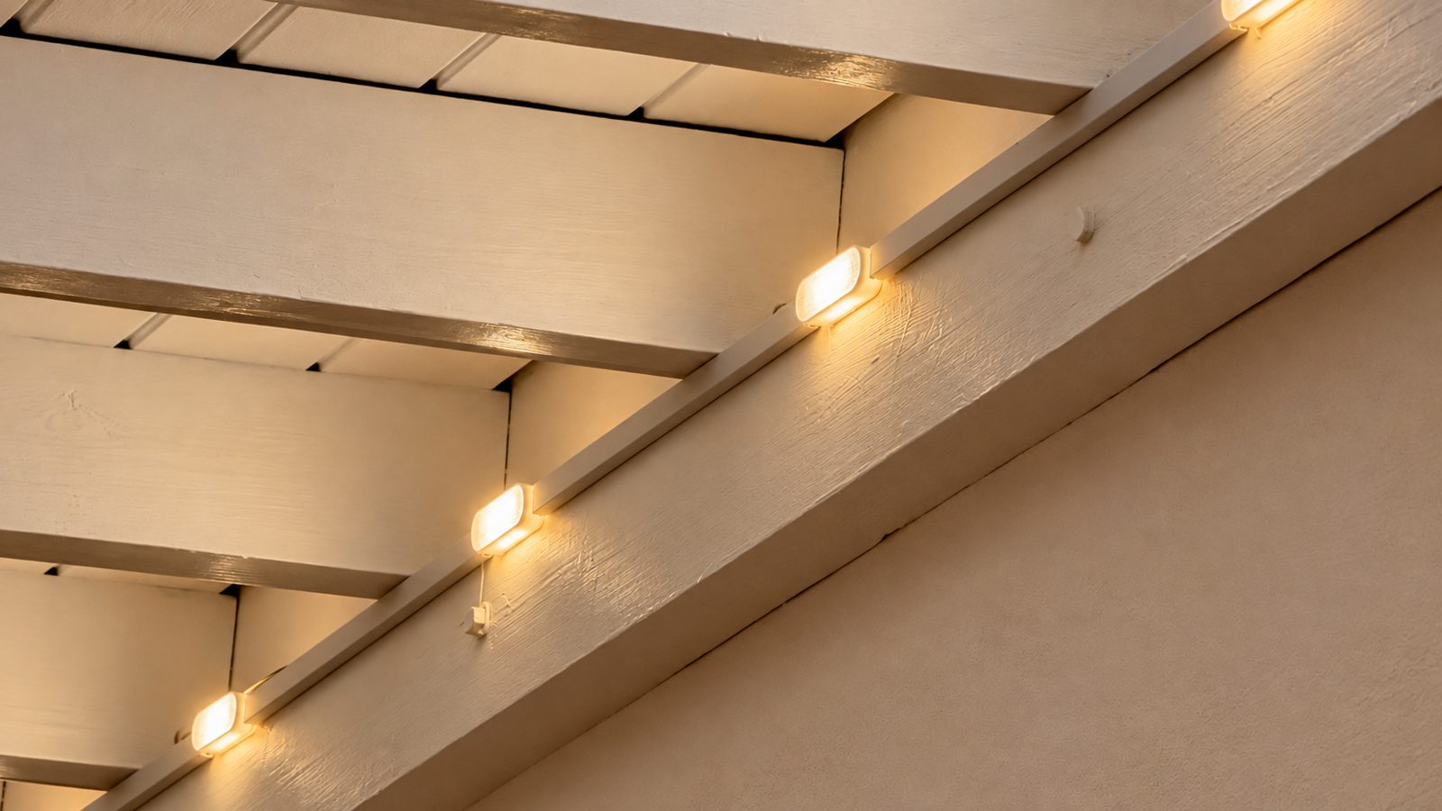
Gloam fixtures lined up along a beam wash the ceiling boards in amber light
Difficulty
Intermediate: soldering and simple wiring
Time
A weekend (printing 16 fixtures not included)
Licence
Firmware MIT · print files and docs CC BY 4.0
The beam line at an angle; fixtures sit at even intervals
Close-up: oval body, frosted diffuser and the channel carrying the cable

Product

A body, two strips, one diffuser

Amber and warm white together: soft, warm everyday light.
Amber only: candle-warm light for evenings and night.
Warm white only: 3000 K.
Exploded view: white PETG body, 5 cm amber and 5 cm warm white COB strips, soldered leads and the frosted diffuser.
From above: the 27 × 90 mm oval body and frosted diffuser.
Cable entry: a 7.5 × 7 mm arch for ~6 mm round cable.

In use

On the beam, at night

On the beam: fixtures spaced evenly, the cable hidden in its channel.
Close up: the frosted diffuser spreads the light softly over the beam.

Controller

Power supply and board in one box

Controller box: USB slot, mounting ears, vents and two cable glands.
Inside: the Mean Well LRS-75-12, the mains divider and the 5 × 7 cm controller board.

Images rendered in Blender from the print files and the CAD model.

What it does

Two lights, one line

  • Amber and warm white

    Two colours in every fixture. Amber alone in the evening, warm white for everyday light, or both; each channel dims on its own.

  • Effects

    Candle, fireplace, breathe, flicker and cloud. They run on the device and are picked from its own page or from Home Assistant.

  • Works on its own

    No app, account or internet needed: on your home network the device serves its own control page, a wall switch lights the last scene and the evening schedule runs on the device. Home Assistant is optional; if you have it, it finds the device by itself and both work at the same time.

  • Its own setup screen

    On first boot it opens a setup network you join from your phone. Once on your home network, it never opens it again.

What you need

Tools, time and parts

Tools

  • 3D printer that prints PETG
  • Soldering iron and solder
  • Wire stripper, side cutter
  • Computer with USB and Chrome or Edge
  • Multimeter (recommended)

Time

Printing: about 1 hour per fixture. Soldering and wiring: 3 to 4 hours. Firmware and setup: 10 minutes.

Parts list

PartQtyNote
Wemos D1 mini (ESP8266)1A NodeMCU v2 works too; same pins.
ULN2003A (DIP-16)1Two outputs in parallel per channel, about 0.8 A.
Mean Well LRS-75-12 power supply (12 V 6 A)1Fully enclosed; the box is designed around it. Covers 16 fixtures. LRS-50-12 also fits (set PSU_Y = 82 in the CAD).
12 V → 5 V step-down (Mini-360 or MP1584)1Powers the D1 mini from the 12 V line.
12 V COB LED strip, amber (~1800 K)5 cm × fixtureCut at the marked points.
12 V COB LED strip, warm white (3000 K)5 cm × fixtureCut at the marked points.
3-core 0.5 mm² cableLine length+12 V, amber −, warm white −. Tested on an 18 m line with 16 fixtures.
5 × 7 cm double-sided perfboard1Controller board; sits on four standoffs in the box.
KF301-3P 5.08 mm terminal block2For the LED line and the 12 V input.
PG11 cable gland, Ø5–10 mm1Mains cable entry.
PG7 cable gland, Ø3–7 mm1LED line exit.
M3 brass heat-set insert4For a Ø4.0 mm hole; press in with a soldering iron at ~230 °C.
M3 × 8 countersunk socket screw (DIN 7991)4Lid screws.
M2 × 6 self-tapping screw for plastic4Holds the perfboard on its standoffs.
4 mm countersunk screw2Mounts the box on a wall or beam.
PETG filament, white and clear~300 g + ~100 gBody and controller box white, diffuser clear.
Cable channelLine lengthOptional; hides the cable along the beam.

Files

Download the files

Everything downloads from this page; no account needed. There is also an all-in-one package.

All in one (.zip)

Print files

Suggested: PETG, 0.2 mm layers, 15% infill. Body in white, diffuser in clear.

  • Fixture body

    STL · 27 × 90 × 16 mm · white PETG

  • Diffuser

    STL · 25 × 88 × 4 mm · clear PETG

  • Controller box

    STL · 135 × 161 × 34 mm · 185 mm with the ears · white PETG

  • Controller lid

    STL · in print orientation, top face down · white PETG

CAD

STEP opens in any CAD program (SolidWorks, Fusion, FreeCAD, Onshape). Parametric sources (CadQuery) are in the repository: hardware/cad.

Electronics

Firmware

Built on ESPHome. Source comes with the editable ESPHome configuration and the setup screen.

Source and history

  • Repository

    GitHub · code, print files, docs

  • Issues

    Report a problem or suggest a change

  • Releases

    Version history and binaries

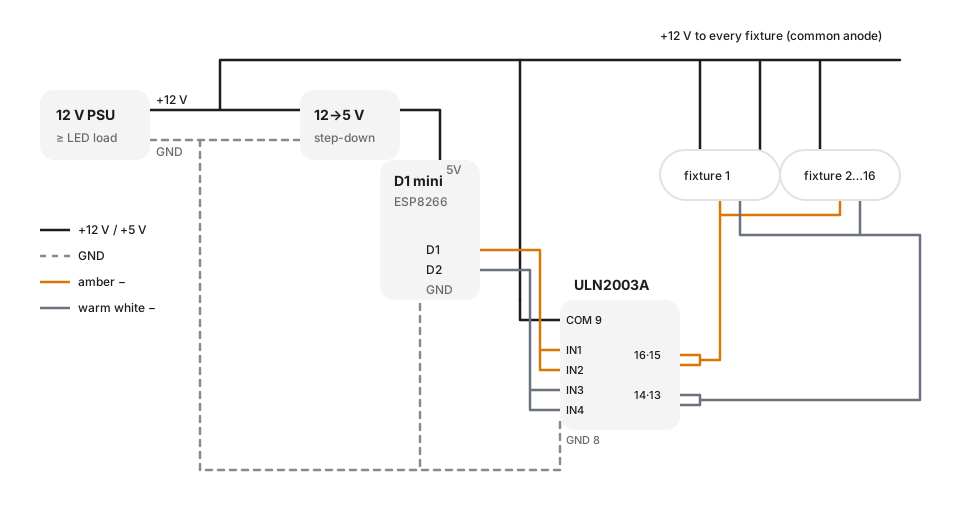
Wiring diagram: 12 V power supply, 5 V step-down, D1 mini, ULN2003A and fixtures

Setup

Flash, connect, use

  1. 01

    Flash the firmware

    Plug the D1 mini into your computer over USB and open the setup wizard. It flashes the firmware and joins Wi-Fi.

  2. 02

    Join Wi-Fi

    Already flashed? When the board starts without a home network, a network called gloam-xxxxxx appears on your phone. Join it and pick your home network on the setup screen.

  3. 03

    Open it on your phone

    On a phone on your home network, open gloam-xxxxxx.local; if it does not open, use the IP address listed next to gloam in your router. The page shows how to put it on your home screen: on iPhone Share › Add to Home Screen, on Android ⋮ › Add to home screen. From then on it opens with one tap like an app; nothing to download.

  4. 04

    Add to Home Assistant if you like

    Gloam shows up under Discovered in Settings › Devices & services. Press Add; the encrypted link sets itself up. The control page keeps working.

  5. 05

    Reset if needed

    Cut and restore power 5 times, each time within 10 seconds: Gloam returns to factory settings and the setup network opens again.

Open the setup wizard

Build

Step by step

Assembly · The strips drop into the body, the cable feeds in at the end, the diffuser closes and the light comes on.
  1. 01

    Print

    Print one body and one diffuser per fixture. The controller box is two parts: box and lid. Press four M3 heat-set inserts into the corner columns of the box.

  2. 02

    Fit the LEDs

    Stick 5 cm of amber and 5 cm of warm white COB strip into each body. Join the plus ends of both strips; keep the minus ends separate.

  3. 03

    Solder the line

    Run the 3-core 0.5 mm² cable from fixture to fixture: +12 V shared, amber minus and warm white minus separate. Fixtures are wired in parallel.

  4. 04

    Build the controller

    Following the wiring diagram, put the 5 V step-down, the D1 mini, the ULN2003A and two terminal blocks on the 5 × 7 cm perfboard. D1 goes to the two amber inputs (IN1, IN2), D2 to the two warm white inputs (IN3, IN4). Seat the power supply in its corner stops and the board on its four standoffs; mains comes in through the PG11 gland, the LED line leaves through PG7, earth goes to FG.

  5. 05

    Check

    Before powering up, measure that 12 V and ground are not shorted. Flash the firmware; on the control page (or in Home Assistant) run Amber and Warm white separately at 10% and 100%. Every fixture should light in both colours; the ULN2003A may get warm but never too hot to touch.

  6. 06

    Mount

    Space the fixtures evenly along the beam, lay the cable in the channel and close the controller box with four M3 screws.

Makers

I made one

Photos and notes from people who built Gloam. Add yours: a photo, a short note, the version, materials and print settings.

Sign in to take part

Use your NOQ account: a code by WhatsApp or email, no password. The same account works on noq.works and the NOQ app.

Questions

Ask where you got stuck

Write your question; Luma answers right away from the project documents and cites its sources. If the documents don't cover it, Luma passes it to the team; it is marked once the team verifies it.

Sign in to take part

Use your NOQ account: a code by WhatsApp or email, no password. The same account works on noq.works and the NOQ app.

Suggestions

What should the next version have?

Suggest an idea or vote for one you like. Planned suggestions go into the release notes with your name.

Sign in to take part

Use your NOQ account: a code by WhatsApp or email, no password. The same account works on noq.works and the NOQ app.

Versions

What changed, what's next

Versions are MAJOR.MINOR.PATCH: a patch fixes, a minor release adds compatible features, a major release needs new parts or wiring.

3 November 2026 · current

Gloam 1.2.1

The control page goes on your phone's home screen like an app, and shows how to put it there.

Firmware

  • Added to the home screen, the control page shows the NOQ Open icon and the device's name and opens full screen (iPhone and Android).
  • On first visit the control page shows, step by step for the phone in hand, how to add it to the home screen; once hidden it stays hidden.

Setup

  • The last step of the setup page mentions adding the control page to the home screen.
Compatibility
Hardware, wiring and settings unchanged; updating from 1.2.0 keeps Wi-Fi and all settings.

Earlier versions

Gloam 1.2.0 · 3 November 2026

Works without Home Assistant: the device serves its own control page, a wall switch lights it and the schedule runs on the device. Home Assistant stays optional and works at the same time.

Firmware

  • Control page on the device: open http://gloam-xxxxxx.local on the home network for both channels, brightness, effects, schedule and power-on behaviour. No app, account or internet needed; it can be added to the phone's home screen. (@umut)
  • Home Assistant and the control page work at the same time on the same lights; a change on one shows up on the other at once.
  • Power on: light up with the last scene (default, so a plain wall switch works), as before the power cut, or stay off.
  • Daily schedule on the device: at the on time the last scene rises over the fade-in time (20 minutes by default), at the off time it fades out. The clock comes from the internet; the time zone is taken from the phone on the control page.

Setup

  • The last step of the setup page shows the device's own address, with Home Assistant as the optional second step.
Compatibility
Hardware and wiring unchanged. Update with the browser installer or ESPHome; Wi-Fi and light settings are kept (do not choose erase). After the update power coming back lights the last scene; choose "As before the power cut" on the control page for the old behaviour.
Thanks
@umut (öneri: Home Assistant olmadan da çalışsın)

Gloam 1.1.0 · 3 November 2026

A new controller enclosure built around the real parts, and editable CAD sources for every printed part.

Hardware

  • Controller enclosure redesigned around the parts in the list: Mean Well LRS-75-12, a 50 × 70 mm perfboard, a PG11 mains gland and a PG7 LED gland on the same end wall.
  • A divider and a rib under the lid keep the mains terminals and wiring apart from the 12 V side.
  • Lid with four M3 countersunk screws in heat-set inserts, a locating lip, vents above the power supply and pads that hold it down; a USB slot for the D1 mini; two mounting ears.
  • The inner plate is gone: the perfboard sits on standoffs in the box floor.
  • Editable CAD sources (CadQuery) for every printed part, STEP files that open in any CAD program, and an assembly STEP with the power supply, perfboard and glands for checking the fit.
  • Fixture body and diffuser rebuilt as parametric models with the same dimensions; parts printed from 1.0.0 still fit.
Compatibility
Fixtures, firmware and wiring are unchanged. The controller is a new two-part set (box and lid) that needs a PG11 and a PG7 gland, four M3 heat-set inserts, four M3 × 8 countersunk screws and four M2 × 6 screws; a controller built from 1.0.0 keeps working.

Gloam 1.0.0 · 2 November 2026

First open release.

Hardware

  • Oval fixture body and plain diffuser; three-part controller box (box, lid, inner plate) for M3 heat-set inserts.
  • Since the prototype: the cable entry at both ends of the body is a 7.5 × 7 mm arch for ~6 mm round cable.
  • Since the prototype: in the controller box, the four standoffs that overlapped the corner screw moved 9 mm down; inner plate holes are M3 clearance (Ø3.4).

Firmware

  • ESPHome firmware: amber and warm white dimmed separately, effects on the device, Home Assistant discovery with the API key set on first connection.
  • Setup: NOQ Open setup page in Turkish and English on the device's own network, 30-minute setup window, Wi-Fi over USB (Improv), factory reset with five power cycles.

Setup

  • Browser installer: write the firmware and set Wi-Fi from open.noq.works/install/gloam, nothing to install.

Documentation

  • Wiring diagram, parts list with suppliers in Turkey, step-by-step build with checks.
Compatibility
First release.
All release notes

Version and licence

Use it, change it, share it

Version
1.2.1 · 3 November 2026 · The control page goes on your phone's home screen like an app, and shows how to put it there.
Firmware
MIT licence
Print files and docs
CC BY 4.0
Attribution
Gloam, NOQ Open · open.noq.works/projects/gloam

Found a bug or made it better? Open an issue on GitHub or write to us; we will fold it into the next release.

3D preview

—

Loading model…

Drag to rotate · Scroll or pinch to zoom

Download